Table of Contents
Advertisement
Statement:
This manual is the intellectual property of Foxconn Inc. Although the
information in this manual may be changed or modified at any time,
Foxconn does not obligate itself to inform the user of these changes.
Trademark:
All trademarks are the property of their respective owners.
Version:
User's Manual V1.0 in English for NF4K8AB series motherboard.
P/N: 91-181-K84-A3-0E
Symbol description:
Note: refers to important information that can help you to use motherboard
better.
Attention: indicates that it may damage hardware or cause data loss,
and tells you how to avoid such problems.
Warning: means that a potential risk of property damage or physical
injury exists.
More information:
If you want more information about our products, please visit the following
website: http://www.foxconnchannel.com
Advertisement
Table of Contents

Related Manuals for WinFast NF4K8AB

Summary of Contents for WinFast NF4K8AB
- Page 1 Foxconn does not obligate itself to inform the user of these changes. Trademark: All trademarks are the property of their respective owners. Version: User’s Manual V1.0 in English for NF4K8AB series motherboard. P/N: 91-181-K84-A3-0E Symbol description: Note: refers to important information that can help you to use motherboard better.
- Page 2 Item Checklist: Thank for your purchasing WinFast NF4K8AB series motherboard. Please check the package; if there are missing or damaged items, contact your distributor as soon as possible. NF4K8AB series motherboard (x1) WinFast Utility CD (x1) User’s Manual (x1) IDE Ribbon Cable (x2)
-
Page 3: Declaration Of Conformity
66 , CHUNG SHAN RD., TU-CHENG INDUSTRIAL DISTRICT, TAIPEI HSIEN, TAIWAN, R.O.C. declares that the product Motherboard NF4K8AB is in conformity with (reference to the specification under which conformity is declared in accordance with 89/336 EEC-EMC Directive) EN 55022/A1: 2000... - Page 4 Declaration of conformity Supplementary Information: This device complies with Part 15 of the FCC Rules. Operation is subject to the following two conditions : (1) this device may not cause harmful interference, and (2) this device must accept any interference received, including interference that may cause undesired operation.
-
Page 5: Table Of Contents
Table of Contents Chapter Product Introduction Main Features ....................2 Motherboard Layout ..................5 Chapter Installation Instructions CPU ......................8 Memory ...................... 12 Power Supply .................... 14 Rear Panel Connectors ................15 Other Connectors ..................17 Expansion Slots ..................21 Jumpers ..................... - Page 6 Table of Contents Chapter Driver CD Introduction Utility CD content ..................Start to install drivers ................. Chapter NVIDIA RAID Introduction Basic Configuration Introductions .............. 53 Setting up the BIOS ..................54 Entering the RAID BIOS Setup ..............55 NVIDIA RAID Utility Installation ..............59 Initializing and Using the Disk Array ............
- Page 7 Warning: 1. Attach the CPU and heatsink using silica gel to ensure full contact. 2. It is suggested to select high-quality, certified fans in order to avoid damage to the motherboard and CPU due to high temperature. 3. Never turn on the machine if the CPU fan is not properly installed. 4.
- Page 8 This manual is suitable for motherboard of NF4K8AB series. Each motherboard is carefully designed for the PC user who wants diverse features. with onboard 100M LAN with onboard 1G LAN with 6-channel audio with 8-channel audio with 1394 with SATA with RAID You can find PPID label on the motherboard.
- Page 9 Chapter Thank you for buying WinFast NF4K8AB series motherboard. This series of motherboard is one of our new products, and offers superior performance, reliability and quality, at a rea- sonable price. This motherboard adopts the advanced NVIDIA nForce4 chipset, providing users a computer platform with a high integration-compatibility-performance price ratio.
-
Page 10: Chapter Product Introduction
RAID 0, RAID 1, RAID 0+1 and JBOD Cross-controller RAID uniquely supports both SATA and PATA disk devices within a single array Onboard LAN (-L/-K) (optional) Supports10/100/1000 (-K optional) Mbps Ethernet LAN interface built-in on board Note: The shielded LAN cables are recommended. NF4K8AB Series User Manual... - Page 11 (suspend to disk-depends on OS), and S5 (soft-off) ACPI state PCI Express x16 Support Supports 4 GB/sec (8GB/sec concurrent) bandwidth Low power consumption and power management features Expansion Slots Three PCI slots Three PCI Express x1 slots One PCI Express x16 Graphics slot NF4K8AB Series User Manual...
- Page 12 Chapter 1 Product Introduction Advanced Features PCI 2.3 Specification Compliant Supports PC Health function (capable of monitoring system voltage, CPU temperature, system temperature, and fan speed) NF4K8AB Series User Manual...
-
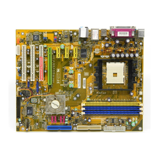
Page 13: Motherboard Layout
28. DDR DIMM slots 29. CPU_FAN connector 30. Socket 754 31. PCI Express x16 slot 32. 12V CPU power connector Note: The above motherboard layout is provided for reference only; please refer to the physical motherboard. NF4K8AB Series User Manual... - Page 14 Please refer to the motherboard layout prior to any installation and read the contents in this chapter carefully. This chapter includes the following information: Memory Power Supply Rear Panel Connectors Other Connectors Expansion Slots Jumpers NF4K8AB Series User Manual...
- Page 15 3. Hold components by their edges to avoid touching any exposed integrated circuits (ICs). 4. Whenever you uninstall a component, place it on a grounded anti- static pad or into the anti-static bag that it came in. NF4K8AB Series User Manual...
-
Page 16: Cpu
When the CPU is in place, press it firmly on the socket while you push down the socket lever to secure the CPU. The lever clicks on the side tab to indicate that it is locked. NF4K8AB Series User Manual... - Page 17 2. If required, apply a light coating of nism base (surrounds the CPU silica gel to the top of the CPU. socket). NOTE: The CPU heatsink may have a pre-applied thermal compound. In that case, the silica gel is not required. NF4K8AB Series User Manual...
- Page 18 5. Push down the retention bracket lock on the retention mechanism to secure the heatsink and fan to module base. 6. Connect the fan’s power cable to the appropriate 3-pin terminal on the motherboard. NF4K8AB Series User Manual...
- Page 19 The following table lists the CPUs that have been tested and qualified for use with this motherboard. Socket Host Bus Speed (Hz) 1.8G Athlon 64 3000+ 2.0G Athlon 64 3200+ 2.2G Athlon 64 3400+ 1.8G Athlon 64 2800+ 2.4G Athlon 64 3700+ 2.0G Sempron 3100+ NF4K8AB Series User Manual...
-
Page 20: Memory
Note: Be sure to unplug the AC power supply before adding or re- moving expansion cards or other system peripherals, espe- cially the memory devices, otherwise your motherboard or the system memory might be seriously damaged. NF4K8AB Series User Manual... - Page 21 (PC2100) DDR 266 SAMSUNG 128MB (PC3200) DDR 400 INFINEON 128MB (PC3200) DDR 400 HYNIX (PC3200) DDR 400 128MB INFINEON (PC3200) DDR 400 256MB CORSAIR (PC3200) DDR 400 512MB KINGSTEK (PC3200) DDR 400 512MB 128MB (PC2700) DDR 333 NF4K8AB Series User Manual...
-
Page 22: Power Supply
G N D G N D Attention: We strongly recommend you use 24-pin power supply. If you want to use 20-pin power supply, you need to align the ATX power connector according to the right picture. NF4K8AB Series User Manual... -
Page 23: Rear Panel Connectors
This 9-pin COM1 port is for pointing devices or other serial devices. Parallel Port: Printer Port The 25-pin port connects a parallel printer, a scanner, or other devices. SPDIF Coaxial Out Port This port connects to external audio output devices with coaxial cable connectors. NF4K8AB Series User Manual... - Page 24 The Microphone jack is used to connect to the microphone. When using a 6-channel sound source, connect the front speaker to the green audio output; connect the surround sound speaker to the blue audio output; connect the center speaker/subwoofer to the red Microphone output. NF4K8AB Series User Manual...
-
Page 25: Other Connectors
LED will flash while the HDD Empty is in operation. FP1! Reset Switch (RESET) Attach the connector to the Reset switch on the front panel of the case; the system will restart when the switch is pressed. NF4K8AB Series User Manual... - Page 26 IRTX The IrDA infrared transmission allows your computer to send and receive data via an infrared ray. The rel- IRRX evant parameters for the BIOS Integrated Peripherals Empty should be set prior to using this function. NF4K8AB Series User Manual...
- Page 27 C D _ I N a u d i o c o n n e c t o r s o n t h e CD_IN motherboard. Speaker Connector: SPEAKER SPKJ The speaker connector is used to connect EMPTY speaker of the chassis. SPK(Pull high) SPEAKER NF4K8AB Series User Manual...
- Page 28 To utilize this function, set “Intruder Detection” to “Enabled” in INTRUDER the “Power Management Setup” section of the CMOS Setup. Save and exit, then boot the oper- ating system once to make sure this function takes effect. NF4K8AB Series User Manual...
-
Page 29: Expansion Slots
PCI Express slot offering 250 MB/sec. Warning: If a performance graphics card was installed to 16x PCI Ex- press slot, 2x12 pin power supply was strongly recommended, since that card maybe drawn 75W power. NF4K8AB Series User Manual... - Page 30 ATI REDION X300SE Radeon x300 128MB WinFast GeForce X5750 GeForce 5750 256MB GeForce PCX 5300 GeForce PCX 5300 128MB ASUS GeForce EN5900 GeForce PCX5900 128MB ASUS Radeon X600SE Radeon X600 pro 128MB graphics cards graphics cards NF4K8AB Series User Manual...
-
Page 31: Jumpers
3. Turn on the system. The BIOS is returned to the default settings. Warning: 1. Disconnect the power cable before adjusting the jumper settings. 2. DO NOT clear the CMOS while the system is turned on. NF4K8AB Series User Manual... - Page 32 The function descriptions herein are just for your reference only. Termination Enable Jumper: J3A2 Termination This jumper is used to enable or disable internal disabled differential termination for PCI Express reference clock input pins. Termination enabled (Default) Termination Enable Jumper NF4K8AB Series User Manual...
- Page 33 PCI Express external reference clock input pins. below VDD/2 (Default) PEX REFCLK Jumper Recovery Jumper: J1E1 Closed This jumper is reserved for technology support, (Default) please do not change the jumper. Open Recovery Jumper NF4K8AB Series User Manual...
- Page 34 Chapter This chapter tells how to change system settings through the BIOS Setup menus. Detailed descriptions of the BIOS param- eters are also provided. You have to run the Setup Program when the following cases occur: T-- This page is intentionally left blank --his 1.
-
Page 35: Chapter Bios Description
The items in the BIOS Setup main menu are explained below: Standard CMOS Features The basic system configuration can be set up through this menu. BIOS Features The general system feature can be set up through this menu. NF4K8AB Series User Manual... - Page 36 Set Supervisor/User Password The supervisor/user password can be set up through this menu. Save & Exit Setup Save CMOS value settings to CMOS and exit setup. Exit Without Saving Abandon all CMOS value changes and exit setup. NF4K8AB Series User Manual...
-
Page 37: Standard Cmos Features
“CHS”, then manually configure the drive by entering the characteristics of the drive directly from the keyboard and pressing < Enter>: Cylinder number of cylinders Head number of heads Precomp write pre-compensation Landing Zone Landing Zone Sector number of sectors NF4K8AB Series User Manual... - Page 38 The BIOS POST will determine the amount of base (or conventional) memory installed in the system. Extended Memory The BIOS determines how much extended memory is present during the POST. Total Memory Total memory of the system. NF4K8AB Series User Manual...
-
Page 39: Bios Features
It is used to set PCI clock. Warning: Make sure your selection is right. Overclocking CPU/PCIE/PCI can adversely affect the reliability of the system and introduce errors into your system. We will not be responsible for any dam- ages caused. NF4K8AB Series User Manual... -
Page 40: Advanced Bios Features
Note: Such function provides protection to the start-up sector only; it does not protect the entire hard disk. CPU Internal Cache (Default: Enabled) This item is used to turn on or off the CPU internal cache. Leave this item at the default value for better performance. NF4K8AB Series User Manual... - Page 41 System, a password is required not only to enter CMOS Setup, but also to start up your PC. Small Logo (EPA) Show (Default: Disabled) This item allows you to enable or disable the EPA logo. NF4K8AB Series User Manual...
-
Page 42: Advanced Chipset Features
Select “Enabled” to allow catching of the system BIOS which may improve per- formance. If any other program writes to this memory area, a system error may result. The available setting values are: Disabled and Enabled. NF4K8AB Series User Manual... - Page 43 If insufficient time is allowed for the RAS to accumulate its charge before DRAM refresh, refreshing may be incomplete and DRAM may fail to retain data. This item applies only when synchronous DRAM is installed in the system. NF4K8AB Series User Manual...
-
Page 44: Integrated Peripherals
MAC Lan (Default: Auto) Setting to Auto allows the BIOS to auto-detect the NVIDIA LAN controller and enable it. Onboard 1394 Controller (Default: Enabled) This item allows you to enable or disable the onboard IEEE 1394 controller. NF4K8AB Series User Manual... - Page 45 This option is used to enable or disable IDE DMA transfer access. Serial-ATA 1/2 (Default: Enabled) This option is used to enable or disable Serial-ATA 1/2. IDE Prefetch Mode (Default: Enabled) This option is used to enable or disable IDE Prefetch Mode. NF4K8AB Series User Manual...
- Page 46 These features allow user to enable or disable the RAID function for each IDE hard disk drive. SATA 0/1/2/3 Master RAID (Default: Disabled) These features allow user to enable or disable the RAID function for each SATA hard disk drive. NF4K8AB Series User Manual...
-
Page 47: Power Management Setup
Power Management (Default: User Define) This option is used to set the power management scheme. Available settings are: User Define, Min Saving and Max Saving. Power Management Events Press <Enter> to set Power Management Events. Please refer to page 41. NF4K8AB Series User Manual... - Page 48 This option is used to set what action the PC will take with the power supply when it resumes after a sudden power failure. The available options are: Off (remain in turn off status),On (auto power on) and Former-Sts (resume with the previous status). NF4K8AB Series User Manual...
- Page 49 This function needs to be supported by the relevant hard- ware and software. USB Resume From S3/S4 (Default: Disabled) This item is used to set the system to wake up by USB equipment when it is in S3/S4 mode. NF4K8AB Series User Manual...
- Page 50 Time (hh:mm:ss) Alarm When the Power-On by Alarm set as Enabled, this option will be modified. It is used to set the timing for the start-up time. NF4K8AB Series User Manual...
-
Page 51: Pnp/Pci Configurations
MPEG audio card problems (e.g., colors not accurately displayed). The setting values are: Disabled and Enabled. Maximum Payload Size (Default:4096 ) Set maximum TLP payload size for the PCI express devices. The unit is byte. NF4K8AB Series User Manual... -
Page 52: Pc Health Status (O.t.s)
This option is used to set the system temperature upper limit. When the temperature exceeds the setting value, the motherboard will automatically cut off power to the computer. The available setting values are: 70 C/158 C/167 F, 80 C/176 F, Disabled. NF4K8AB Series User Manual... -
Page 53: X-Bios Ii
Memory Vmem Select (Default: Default) This option is used to select memory Vmem. HyperTransport Vdd Select (Default: Default) This option is used to select HyperTransport Vdd. CPU Voltage Regulator (Default: Default) This option is used to adjust CPU voltage regulator. NF4K8AB Series User Manual... -
Page 54: Load Best Defaults
Under the menu “Advanced BIOS Features Setup”, if you select “Setup” in Secu- rity Option, the screen will prompt you to enter password only when you enter CMOS setting program. NF4K8AB Series User Manual... -
Page 55: Save & Exit Setup
Select this option and press <Enter>, it will show the following message on the screen: Quit Without Saving (Y/N)? Press <Y> to discard any changes that you have made in the Setup Utility and exit the Setup Utility; press <N>/<ESC> to return to the main menu. NF4K8AB Series User Manual... - Page 56 Chapter The utility CD that came with the motherboard contains useful software and several utility drivers that enhance the mother- board features. This chapter includes the following information: Utility CD content Start to install drivers...
- Page 57 SuperUpdate function can help to update the BIOS through Internet. B. Adobe Reader C. Norton Internet Security D. Word Perfect Office 12 E. nTune 3. Browse CD Click to browse this CD. 4. Homepage Click here to visit Foxconn motherboard homepage. NF4K8AB Series User Manual...
- Page 58 Chapter 4 Driver CD Introduction Start to install drivers Select <Install Driver> to enter the driver installation menu (as following pic). Click the relevant button to install nVIDIA nForce Chipset System, DirectX 9.0b, USB2.0 Driver. Click here NF4K8AB Series User Manual...
- Page 59 Chapter This chapter will introduce how to create NVIDIA RAID. This chapter includes the following information: Basic Configuration Setting up BIOS Entering the RAID BIOS Setup NVIDIA RAID Utility Installation Initializing and Using the Disk Array Win2K Limitation with Bootable RAID...
-
Page 60: Chapter Nvidia Raid Introduction
D e c r e a s e s p e r f o r - Combines and uses multiple JBOD mance because of the the capacity of odd difficulty in using drives size drives. concurrently or to op- timize drives for differ- ent uses. NF4K8AB Series User Manual... -
Page 61: Basic Configuration Instructions
(RAID 0+1), or Spanning (JBOD) and create the desired RAID array. 3. Boot from the Windows CD, then press F6 when the Windows Setup appears. 4. Insert the RAID driver floppy to Install the nForce RAID driver. 5. Initialize the NVRAID Array. NF4K8AB Series User Manual... -
Page 62: Setting Up The Bios
3. From the RAID Config window, enabled the RAID Enable, the other items would be light, then you can enable the disk that you want to use as RAID disks. 4. Press F10 to save the configuration and exit. NF4K8AB Series User Manual... -
Page 63: Entering The Raid Bios Setup
(location) columns of the Free Disks and Array Disks lists. 1. 0. M M: Master S: Slave 0: Channel Adapter - adapter 0 is used for PATA drives 1 and above is used for SATA drives. NF4K8AB Series User Manual... - Page 64 Striping Block size is given in kilobytes, and affects how data is arranged on the disk. It is recommended to leave this value at the default [Optimal], which is 32KB, but the values can be between [4 KB] and [128 KB]. NF4K8AB Series User Manual...
- Page 65 It shows that two disks have been assigned as RAID1 array disks in the figure above. Completing the RAID BIOS Setup 1. After assigning your RAID array mode, press F7. The Clear disk data windows prompt appears. NF4K8AB Series User Manual...
- Page 66 4. If you want to mark this disk as empty and wipe out all its contents then press C. 5. At the prompt, press Y to wipe out all the data, otherwise press N. 6. Press Enter again to go back to the previous window and then press [Ctrl+X] to exit the RAID setup. NF4K8AB Series User Manual...
-
Page 67: Nvidia Raid Utility Installation
2. Select the modules that you want to install. Select the relative options that you have configured. 3. Click Next and then follow the instructions. 4. After the installation is completed, be sure to reboot the PC. 5. After the reboot, initialize the newly created array. NF4K8AB Series User Manual... -
Page 68: Chapter 5 Nvidia Raid Introduction
(2) Select “NVIDIA RAID CLASS DRIVER” and then press Enter. (3) Press S again at the Specify Devices screen, then press Enter. (4) Select “NVIDIA NForce Storage Controller” and then press Enter. The following Windows Setup screen appears listing both drivers: NF4K8AB Series User Manual... - Page 69 Note: Each time you add a new hard drive to a RAID array, the RAID driver will have to be installed under Windows once for that hard drive. After that, the driver will not have to be installed. NF4K8AB Series User Manual...
-
Page 70: Initializing And Using The Disk Array
You must format the unallocated disk space in order to use it. 3. Format the unlocated disk space. Right click “Unallocated space”, select “New Partition…” and follow the wizard. After the drive has been formatted, it is ready for use. NF4K8AB Series User Manual... -
Page 71: Win2K Limitation With Bootable Raid
You should see the single disk RAID array (in striping mode) that was created from the boot disk. 12. Select the single boot disk RAID Array by clicking on it. 13. Select Convert Array under the System Tasks. The Convert Array wizard is displayed. Then Select Next. NF4K8AB Series User Manual... - Page 72 Note: If the end user chooses not to install Windows 2000 Service Pack 3 or 4, RAID is still supported on Windows 2000. However, the end user will not be able to create a bootable RAID volume. NF4K8AB Series User Manual...
-
Page 73: Appendix
2. Using 8-channel Audio STEP 1. Connect the front channels to green jack, the rear channels to black jack, the Center/Subwoofer channels to orange jack and Side channels to blue jack. Please refer to below figure. NF4K8AB Series User Manual... - Page 74 Appendix Blue Black Green Orange STEP 2. You need to install the driver for the audio chip before you can use the 8- channel audio function. Click here NF4K8AB Series User Manual...
- Page 75 Double click the icon, you will see the following picture. Click here STEP 4. Click icon. The following picture will appear. Click here STEP 5. Make sure you select “7.1 Speakers” from the above picture. Now you can enjoy the 8-channel audio function. NF4K8AB Series User Manual...