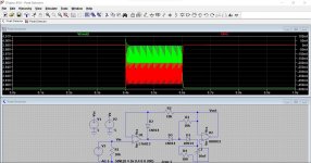
I was planning to use the peak detector described on the Elliot Sounds website:
https://sound-au.com/appnotes/an014.htmSpecifically this one:

However while simulating its response I noticed the maximum peak is limited by VCC/2, can anyone explain this to me?
The circuit in figure 2 is also showing as limited to VCC/2.
How could I alter this circuit to alter this response?
I have +/-5V and I'd like the peak detector to work from 20mV to 3V3 (3V is also acceptable).
I've also tried https://www.analog.com/en/technical-articles/ltc6244-high-speed-peak-detector.html but it is unable to monitor low voltages.
https://sound-au.com/appnotes/an014.htmSpecifically this one:
However while simulating its response I noticed the maximum peak is limited by VCC/2, can anyone explain this to me?
The circuit in figure 2 is also showing as limited to VCC/2.
How could I alter this circuit to alter this response?
I have +/-5V and I'd like the peak detector to work from 20mV to 3V3 (3V is also acceptable).
I've also tried https://www.analog.com/en/technical-articles/ltc6244-high-speed-peak-detector.html but it is unable to monitor low voltages.
What is limited, max input or max output?I was planning to use the peak detector described on the Elliot Sounds website:
https://sound-au.com/appnotes/an014.htmSpecifically this one:
View attachment 1031763
However while simulating its response I noticed the maximum peak is limited by VCC/2, can anyone explain this to me?
The circuit in figure 2 is also showing as limited to VCC/2.
How could I alter this circuit to alter this response?
I have +/-5V and I'd like the peak detector to work from 20mV to 3V3 (3V is also acceptable).
I've also tried https://www.analog.com/en/technical-articles/ltc6244-high-speed-peak-detector.html but it is unable to monitor low voltages.
Jan
Thanks for the replies! Mooly, you're correct, its an issue with the model, I switched out the AD8066 I was using to a similar one and the simulation now works.
Question is, do you think it is a problem with the sim or that I will see this in real life? I suppose I can switch out the AD8066 if I do really find it limiting.
Question is, do you think it is a problem with the sim or that I will see this in real life? I suppose I can switch out the AD8066 if I do really find it limiting.
Possibly a bit of both. -/+ 5v supply is not enough for some real world opamps to get close to the rails. I'm thinking of the TLE2072 opamps which are supposed to be replacements for the TL072's. I've seen that for real myself. If its a DIP opamp thn just fit a socket and then you can see what works.
I wouldn't go exotic for this, just try some jelly bean devices.
I wouldn't go exotic for this, just try some jelly bean devices.
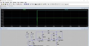
The output voltage is high from the very start. Maybe the op-amp has a negative bias current that charges the hold capacitor.
Regarding the output voltage range, it is limited by the op-amps, but also by the drop across the two diodes.
According to figure 11 of the datasheet, see https://www.analog.com/en/products/ad8031.html#product-overview , the bias current can go negative at high input voltages (which is weird, because you would expect it to use an NPN stage at high common mode voltages and a PNP stage at low voltages - sign inverted somewhere?). It's an op-amp with a bipolar input with way too high bias current to be used as the second op-amp in this circuit.
Last edited:
Looking at figure 43, it indeed uses a PNP differential pair at low and an NPN differential pair at high common mode voltages. The PNP base current charges the hold capacitor until it is at the point where the NPN starts to take over and their base currents cancel, about 0.8 V below the positive supply rail.
The output voltage is high from the very start. Maybe the op-amp has a negative bias current that charges the hold capacitor.
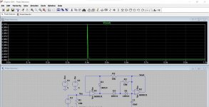
It looks like the input current of this opamp is just magnitudes higher than is desirable for this application. Adding a 100 ohm in series with the input shows a peak input current of nearly 0.5uA
This shows the voltage output and current in the 100 ohm. The input has been changed from 2 cycles to 200 cycles.
Just use a suitable FET opamp, job done.

- Home
- Design & Build
- Equipment & Tools
- Peak Voltage Detector

